
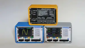
An Introduction to Picotronix
A modular, low-cost test and measurement platform for makers, combining oscilloscope, logic analysis and extensible capabilities.
Powered By Two Raspberry Pi* Pico 2 Modules

… and be nice — tell your friends
Tap any point for more.
Not just an economical modular instrument. A base you can build on.
Where the platform could go: ideas for future development, or build your own
Dual TI 100 MSPS ADC on picoPod. 75 MSPS single channel, 50 MSPS with both channels running.
Single Channel 100 MSPS with the RP2350 overclocked to 200 MHz.**
For lower frequency signals the system drops back automatically to the RP2350's native ADC, trading the pod's 8 bit speed for 12 bit resolution.

8 Logic Inputs ✦ Three Ports for Expansion Pods - 2 Analog, 1 Multifunction ✦ Analog Bus Bandwidth 15 MHz Full Power, 50 MHz Small Signal (1 Vpp) ✦ 10 MHz Bandwidth to the RP2350 ✦ Frequency Counter to 15 MHz ✦ Logic Probe ✦ Voltmeter 0-6 V or 0-16 V ✦ 320 x 240 RGB LCD
Picotronix with 75 MSPS picoPod (as shown) – $179 USD (est*)
Picotronix Base Configuration – $129 USD (est*)
less again for Early Bird Backers
We makers all know about design gremlins… but wait until you try to make a video! Norm, Moose the border collie and Sydney Airport.
Know someone who’d laugh at this, or who needs a scope? Please share it: youtu.be/T8dyUPAssPk
Start with an Open Architecture Picotronix™ Main Module, a versatile, standalone precision instrument. With two analog and one multifunction port for attaching autoconfiguring Application Specific Front-End picoPods, it is a plug-and-go, fit-for-purpose modular test platform for Makers and Engineers.
The Picogram Data Structure and AI
Picotronix uses Picogram, our data structure, to communicate between the Signal Acquisition RP2350 and the Display Control RP2350. The same structure is designed to send signal data direct to a smart phone or PC for further processing or more detailed display, and to let an AI obtain the raw signal data, process it, suggest further probing and suggest a fix. The capability is here; the software is being developed in stages.
In this four minute introduction, Norm shows the Picotronix Main Module inside and out: the 320 x 240 colour LCD, the rear panel PCB that doubles as the power board and a printed quick reference, and power from USB-C or four internal AAA cells for portable use. Inside, a Pico 2 W drives the display while a second Pico 2 works as the DSP capturing the data. He also shows the built-in simulation modes useful for education, then runs the DSO alongside a Tektronix bench scope on a shared signal generator, tracking sine, triangle and square waves, with the RP2350's ADC producing a clean triangle wave free of power-of-two discontinuities or other artifacts.
 WiFi or USB link
 Remote Data Logger
In this uncut 21 minute walkthrough, Norm powers up the Picotronix Main Module and works through its virtual instruments, with a Tektronix TBS 2000 alongside as a bench reference. He demonstrates the two channel DSO with trigger source, polarity and level control, A/B and interleaved dual channel capture on the RP2350's native 500 kSPS 12 bit ADC, and timebases from 5 ms down to 10 µs per division. Along the way he shows the phosphor style display that reveals the noise floor while averaging keeps the trace clean, even using just 5% of the ADC range, and is straightforward about where the base unit reaches its limits and how the 100 MSPS Multisignal picoPod extends it.
Dive into the details of the Picotronix Main Module and expansion modules at picoPods


A modular, low-cost test and measurement platform for makers, combining oscilloscope, logic analysis and extensible capabilities.
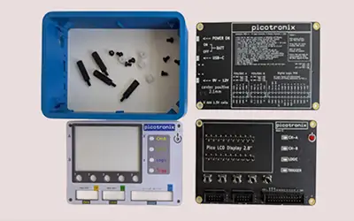
Picotronix is currently housed in a simple 3D printed extruded case. The design uses the MainBoard and the back Power board to enclose the circuits. A front panel made from a blank PCB completes the assembly making it a very minimal and practical design solution.

Inter-pico communications using datagrams based on msgpack formats on micropython. Dictionary based data structures provide an easy way to send detailed message protocols without having to predefine the structure.
* Kickstarter requires us to set pledge levels in Australian dollars. US dollar figures shown are estimates and will vary with the exchange rate at the time you pledge.
** Overclocking the RP2350 beyond its specified clock rate is optional, and is undertaken at the user's own risk.