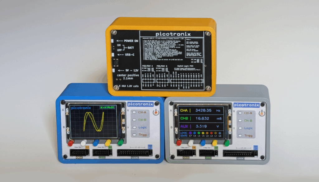
Picotronix – a Modular Test and Measurement platform
This design – picotronix – is essentially a low cost framework for electronic test and measurement based on Raspberry Pi Pico 2 modules. It is an extensible set of components (including software) that interoperate to implement a wide range of test equipment.
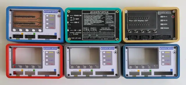
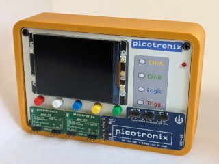
The MainBoard incorporates the pico modules, LCD, UI and Port connectors to external circuits. Basic functionality can be extended by plugging in specialized adapters to any of the Port connectors, which extend the functionality and become part of the picotronix ecosystem.
picotronix can be stand alone – it has a built in LCD display and user control buttons. As well, the main pico 2 is wifi enabled so it can link to an external device like a PC or phone. In that case picotronix becomes a peripheral device.
Test Equipment for Makers
If you are a maker or student exploring the world of electronics and circuits, an oscilloscope and a logic analyzer are really useful tools to have on your workbench. These devices let you measure, observe and analyze what your gadget is actually doing.
The Oscilloscope looks at actual analog signals and shows you the shape, size and frequency of the electrical points of interest. A great example would be looking at a circuit that processes audio signals like a headphone amplifier.
The Logic Analyser looks at a set of logic signals in your circuit and records their changes over time. This can help debug circuits like servo controls or other robotic sensor signals. Often, a microcontroller like Raspberry Pi Pico is the core of the design, so the signals are controlled by software. Looking at the actual signal timing can quickly show if the software code is doing what it is supposed to.
A piece of equipment that lets you see what is happening in your maker project is definitely a very useful addition to your toolkit. Typically, Oscilloscopes and Logic Analysers do a lot more than a student or experimenter really needs. Sometimes you need both, and having them in a single package will be a big time saver and picotronix won’t break the bank.
What can picotronix be used for?
- A 2 Channel Oscilloscope lets you look at analog waveforms
- 8 Channel logic Analyser for timing and I2c or SPI
- Voltage and Frequency measurement of signals
With the addition of specialized POD adapters, picotronix can be extended to include Waveform Generators, High Speed Flash ADC converters, Variable Threshold Logic inputs, and special purpose adapters.
How fast is picotronix?
picotronix makes use of the PIO circuits in the RP2350 at the core of pico 2. These state machines can clock at up to 150MHz, but due to internal DMA transfers, 100MB/s is the practical limit. The Logic Bus inputs can transfer to internal SRAM at high speeds so resolving logic edges to about 10nS is possible.
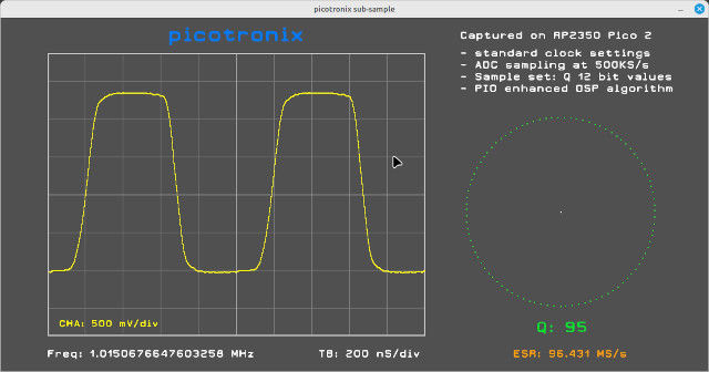
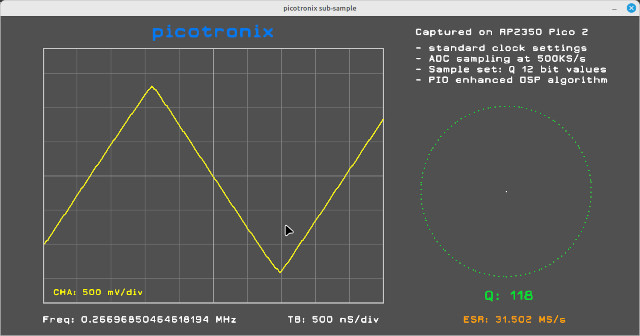
The picotronix main board uses the RP2350 12bit ADC to capture analog signals, and the input stages are specified to have a 20MHz bandwidth at 3Vpp. In normal operation the ADC captures at 500KS/s, so that supports a timebase of up to 10uS/div.
The RP2350 ADC has a bandwidth of about 10MHz (not to be confused with sample rate ). With the help of the PIO state machines and some DSP magic, a much higher ESR (Effective Sample Rate) can be achieved for repeating signals. We will be covering this topic in a future blog post, but here is a sample of what can be achieved on a stock pico 2. These captures were done using a Python GUI running on a PC, connected via wifi to the picotronix.