Making a Case for Picotronix
Simple case design with minimal components
A Test Instrument that is part of an Electronics Workbench needs to have a case. This makes it portable, robust, and protects the internal circuits.
The case design we came up with is a simple extrusion (3DPrint or Injection Mould) which uses the main PCB and the Power PCB as the front and back. This case is basically four 5mm walls straight up, so it is an easy 3D print, and translates directly to an Injection Mould.
To hold the PCB in place, each corner has a shoulder that captures a 20mm nylon hex spacer, and also the walls have several 20mm ribs which support the PCB and prevent flexing.
Shoulder brackets hold the spacers
Making a Front Panel
The front panel sits 6mm above the MainBoard. This guides the User Buttons, provides a back plate for the LCD, covers the Ports and shows the indicator LEDs.
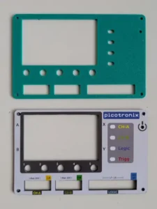
PCB material with printed label
The panel is just a blank PCB with cutouts and it gets a Lexal label attached to the front. A blank PCB is very tough and the PCB process gives accurate cutout dimensions. This solution is cheap and practical.
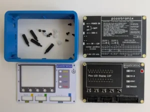
The assembled stack
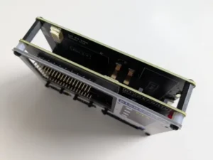
Assembled PCB (main and back) with Front Panel
With the 20mm spacers, this is a solid and robust assembled stack. The shoulders and ribs in the main case are trapped between the two PCBs, so when the unit is fully assembled it is absolutely stable.
LED Indicators
The picotronix MainBoard has four indicator LEDs which are under software control. CHA, CHB, Logic and Trigger. These signal operational state according to the Virtual Instrument being run.
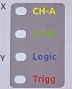
To make these LEDs subtle and avoid mechanical mounting issues, these LEDs are SMD devices located on the front of the MainBoard. The front panel has cutouts for these and the Label is a matching white translucent print. The LEDs shine through the cutout and make the label glow in the LED color. LEDs (particularly Blue LEDs) can be very bright and annoying if viewed directly. You just want a soft glow from the indicators.
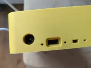
Power Connector access
The back PCB of the case is also the power supply board. The case has cutouts for various power connectors and options. A USB-C socket allows a phone charger to power the device, while a DC-Jack will accept a 9-12V plug if you have any of those available.
The small rectangle cutout to the right gives access to a tiny slide switch to activate the 4 AAA cells on the PCB. This is typically for emergencies or special cases where you need a portable instrument with no power cables. To access the switch you probably need a paperclip or one of those little metal pins that come with a mobile phone. The battery option is not meant to be convenient.
We chose AAA non-rechargeable batteries because they are common, cheap, and don’t cause a problem with baggage rules. Changing them just requires 4 screws at the back and taking out the back PCB. A fresh set of AAA batteries should provide about 8 hours of use. The main drain is the LCD backlight, so software can monitor activity and dim the backlights after a few minutes.
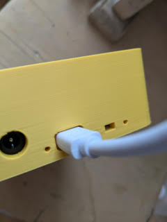
The USB receptacle is designed to take the fattest USB connector – which seems to be the Raspberry Pi USB power cable.
Power LED Indicators
The Power PCB has 3 LEDs – DC, USB and system Power. To see these LEDs we put holes in the case side to let the light out. If you are thinking that these holes look suspiciously like 1.75mm holes that match 3D print filament, you would be correct!
A short section of clear 3D print filament will fit in each hole, making a light pipe to the LED on the Power PCB. The filaments need to be trimmed to the correct length and pushed flush with the case exterior. Simple.
![]()
The 3D Print Option
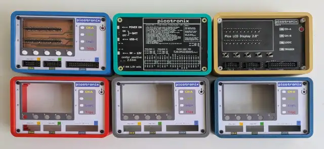
Having a Case design that is easy to 3D print has some advantages. During development problems are quickly fixed so iteration is fast and cheap. It is also possible to try various color options to see what works.
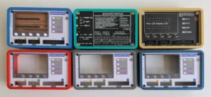
So far, the “Bermuda Blue” followed by the “Gold” seems to be popular amongst people who have seen the case up close.
Picotronix is expected to launch on KickStarter, so we intend to use a small 3D print farm to cover the first 500 units. 500-1000 is the quantity required to justify an Injection Mould run, after which we will supply the IM version (probably blue). Anyone who orders a Printed case will get an IM case for free (after we get past 500 units).
To make it interesting, the Printed cases will be in limited 100 batches of various colours, so if you really want a pink one you might want to get in quick. Yes, pink 3D print filament is definitely a thing.
Where did I put that Manual?
Someone once said that the best part is no part. The corollary to that is to make every part provide as many functions as possible. In our case, the back of the unit is a PCB that encloses the unit and also provides the power circuitry. That is two functions. What about all the PCB real estate on the back of the PCB? Why not put a cheat sheet with guides to pinouts and basic functions on the back?
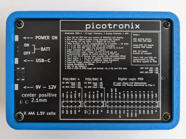
Pinout guide on the back panel
The final assembly
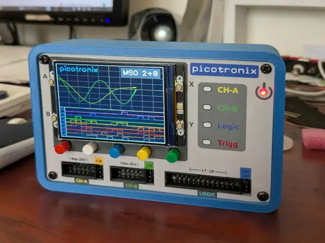
This is what an assembled unit should look like.
The case walls are 5mm thick, so it is quite durable. Even 3dp PLA shows no sign of cracking, splitting or delamination with drop tests and giving the case a light wack with a hammer. Eventually, the hammer will win, so don’t do that. The most vulnerable part of the design is the LCD module, which should be protected from impacts or sharp edges.