An Introduction to Picotronix
A modular, low-cost test and measurement platform for makers, combining oscilloscope, logic analysis and extensible capabilities.

Swipe or pick from the menu
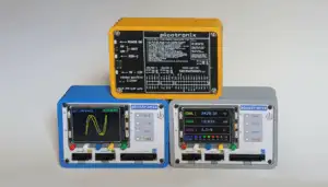
Picotronix is a user configurable, versatile, cost effective and modular precision instrument that can handle multiple types of signal processing simultaneously. You are looking at the Picotronix Command Module that includes the Picotronix Main Board, Power Module (with battery support) and a Case.
It provides a modular interface between the Real World (Analog & Digital Domains) and the Programmable State Machines of the Raspberry Pi RP2350 – maximising the Pi's inherent capabilities and extending them deeply into the Test and Measurement (T&M) ecosystem. This is achieved by the use of special function autoconfiguring, modules (picoPods) that attach to Ports on the Command Module. This modular approach allows you to choose the optimal solution for your specific test and measurement requirements.
You are viewing analog and digital signals that are output by the Command Module to a PC, using our Picogram comms protocol.
Multiple signal processing capabilities with professional-grade precision in a compact, cost-effective package. The results are displayed on the optional local LCD using the Local Python Display Engine and/or on a Remote Display (e.g., PC), using the functionally equivalent Remote Python Display Engine.
The standardised port structure, AI friendly compartmentalised software architecture, and a backbone of Open Source Software, facilitates custom solutions and pod designs, for configurations outside our extensive and growing library of Pods.
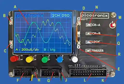
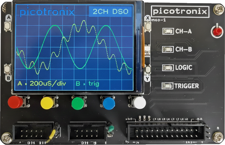
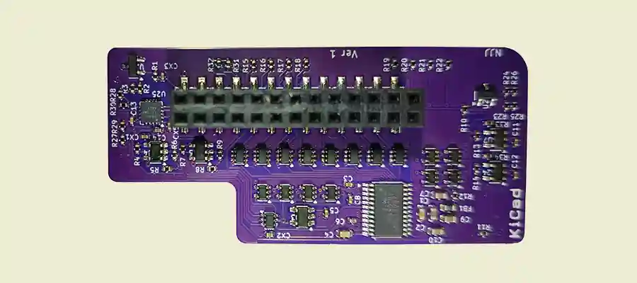
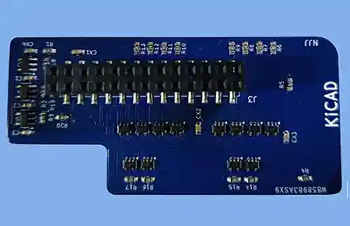
The Picotronix Motherboard packs approximately 142 components onto a compact 125mm x 80mm PCB. The standard configuration includes a 320 x 240 display (A) that is easily driven by the Pico 2W module outputting the required analog and digital profiles in real time. The RP2350 truly is a powerhouse in a small package!
The Picotronix platform offers three flexible display configurations to suit your application needs:
a) Local display using a 320×240 colour LCD connected directly to the Motherboard's mating socket – operable without any external display
b) Remote display operation with no LCD attached to the Motherboard, utilising external devices (PC, smartphone, laptop) for all display functions – ideal for remote data logging and cost-effective applications
c) Combination mode offering flexible configurations of both the local LCD and remote display. Options include remote mirroring of the local display, local mirroring the remote display (within resolution limits), or mixed functions where the local display shows basic information whilst the remote device provides detailed analysis, longer time-base traces, and enhanced signal processing capabilities.
This modular approach allows you to choose the optimal display solution for your specific test and measurement requirements.
The Picotronix Host Platform features two 10-pin (5×2) analog ports for receiving analog signals:
Yellow channel on display
Green channel on display
Each port offers two alternative analog inputs:
Input 1: 3 volt peak-to-peak (3Vpp) signal
Input 2: 16.6Vpp signal
While analog signals can be applied directly to port pins, coupling is typically achieved via analog pods that plug into the ports.
Adjacent to each main port are supplementary analog input pairs:
BNC 16.6Vpp AC input
BNC 16.6Vpp DC input
These inputs share buffers, offset, and trigger circuitry with Channel A Port
Only one of the four Channel A inputs can be used simultaneously
Identical to Channel A supplementary inputs
These share buffers, offset, and trigger circuitry with the Channel B Port
Only one of the four Channel B inputs can be used simultaneously
All Primary inputs feature 1 Mega Ohm impedance
The Auxiliary Port provides two additional analog inputs (one selectable at a time):
6.6V Input: 0-6.6 volts at 4kΩ impedance
16.7V Input: 0-16.7 volts at 100kΩ impedance
Note: Auxiliary inputs have limited protection, no offset capability, and no trigger functionality.
Instant logic testing without full system setup! The 6.6V auxiliary channel doubles as a simple Logic State Probe, sharing the Trigger LED (R) to indicate logic high states. This valuable troubleshooting tool works even in bare-bones configuration—just add power, no Pico2 modules required!
Out of the box Voltmeter! The default setup of the Auxiliary Port is User selectable between a Logic Probe on the 6.6 volt input or a Voltmeter on the 16.7 volt input!
The Command Module can simultaneously receive up to three different analog signals with ten different input pins to choose from, providing exceptional flexibility for diverse measurement scenarios.
The Analog Pod provide signal conditioning to ensure all inputs meet the Picotronix and RP2350 requirements while simultaneously serving as a gateway for customized signal pre-processing capabilities. While our standard picoPods showcase several innovative preprocessing methods, the true potential lies in user customisation.
The 26 pin (13 x 2) Multifunction Port includes mixed signal types, including outputs of the Channel A & B signals conditioned to the 0-3 volt range required by the RP2350, and 12 general purpose digital I/O lines that are buffered and protected before coupling to the RP2350 pins (and also pulled to a known logic level if left floating).
Eight of the Data Lines are typically dedicated to data transfer (for example, 8 bits for logic state analysis, or digitised analog data from an ADC). The remaining four lines may be for data transfer (e.g., providing for a total of 12 bits for LSA), control, or clocks etc.
By setting the Triggers on Channel A and or B to logic levels, the analog inputs on the analog ports can be configured to work in conjunction with the Multifunction Port (L) for a total of 14 inputs for Logic State Analysis (LSA).
With an LSA Pod in Port (L), Picotronix may receive data from up to five different logic families.
Our typical Multifunction Port picoPods handle analog capture, logic analysis, mixed-signal measurement, and waveform generation.
Beyond these comprehensive T&M capabilities, the High Speed 12-bit bus of the Port offers extended possibilities—specialized data acquisition systems, research prototypes, or any electronics leveraging our digital infrastructure, Pi processing power, or remote computer interfacing for extended processing and control.
Perfect for T&M professionals seeking advanced capabilities, researchers needing rapid prototyping support, and the vast Pi community wanting professional-grade signal conditioning and data handling—all with familiar RP2350 development tools. Plus, you retain direct access to 12 Pi I/O channels for unlimited creativity.
The Power On LED (M) is active whenever there is power to the module. This may be supplied from a USB cable attached to the Pico 2W Module, or from the integrated Power Module (Battery, USB or 9-12v Plug Pack).
The Channel A LED (N), Channel B Led (P) and Logic LED (Q) are software configurable to indicate various functions pertaining to signals coupled to analog input pins on (F)+(H); (G)+(J), and Port (L) respectively. They are under the control of the Display/Control Processor.
The Trigger LED (R) is under control of the Signal Acquisition Processor and programmable to indicate various events pertaining to either of the analog input triggers. It is also used to indicate a Logic High when Input (K) is used as a Logic State Probe.
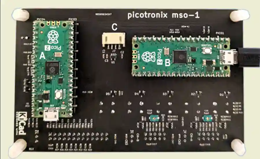
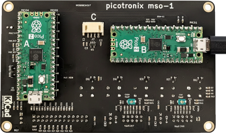
Two RP2350's are used to drive Picotronix:
The Pico 2 (A) is the Signal Processing Unit, providing signal capture and preliminary processing. It controls the Trigger LED, Trigger Level, Signal Offset, Signal Noise Injection and Negative Bias.
The Pico2W (B) is the Display/Control Processing Unit, managing control functions, pod recognition, display operations and remote interfacing. The Pico2W can connect to a remote computer (PC, Smart Phone) via its integrated WiFi.
Both Pico2 Modules are socketed, providing a simple upgrade path to RP2350 Modules with increased memory, future enhanced RP2350 variants, and any compatible upcoming family members.
The separation of Signal Processing functions from those for Display/Control functions, allows independent development of software and optimisation for each of the functional modules, while maintaining system coherence through well-defined communication protocols.
We use a Picogram (a Datagram Structure) for information exchange between the two RP2350's and between the RP2350's and Remote Processors.
The 4-pin connector (U) provides an interface for the optional power module to connect to the picoPlat by a cable.
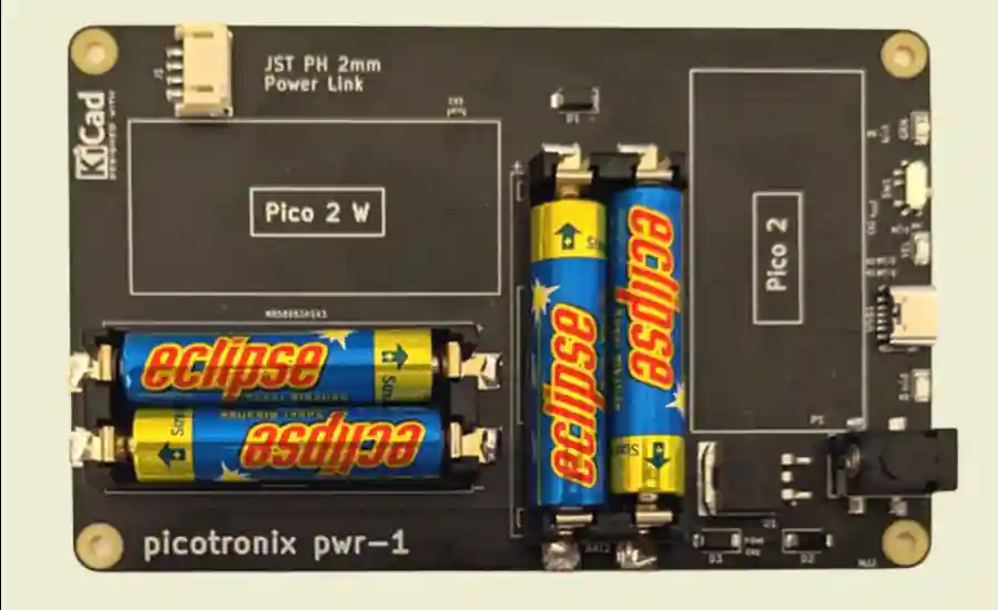
The Picotronix may have power supplied by a USB cable attached to the Pico 2W module. The Picotronix Power module, provides three alternative methods of powering the system:
Power supplied by a USB cable plugged into the USB connector (A) on the Power Module.
A 9-12 volt plug pack attached to connector (B).
Four Triple A (AAA) Non- Rechargeable Batteries (C) that may come in handy if needing to work in an awkward location or if there is no mains power source available. Come to think of it, Any Reason You Like!!!
The Green LED (D) indicates that power is being supplied to the system.
The Slider Switch (E) adjacent to the Green LED (D) disables/enables battery power to the system. It is enabled if the slider is in the position closest to the Green LED (D).
The Yellow LED (F) indicates that the board is receiving power from a USB cable.
The Red LED (G) indicates that the board is receiving power from a 9-12 volt Plug Pack.
*It is important to note that although the Yellow or Red Led may be ON, if the Slider Switch (E) is set to supply battery power to Picotronix, the batteries will take precedence.*
Only slightly larger than a Raspberry Pi Pico 2, this compact purple picoPod packs a punch. Attaching to the Multifunction Port of The Platform, it includes a 100 Mega Samples Per Second (MSPS), 8-bit Analog to Digital Converter (ADC):
The Analog 'A' and 'B' Channels from the Command Module Analog Ports are routed to the ADC via a multiplexer, providing access to any analog signal directly input to Channel A or B, or preconditioned by an Analog Pod coupled to these Channels.
Either the 'A' or the 'B' Channel may be selected for conversion at the maximum rate of 100 MSPS.
However, as the current RP2350 is only rated at 150 MHz, and as each sample requires two clock pulses, sampling peaks at 75 MSPS.
Unless of course, you are not terrified by the RP2350 specs.
So, Overclockers – go for it (at your risk!).
We expect that future versions of the RP2350 may have a faster clock capable of fully utilising the 'Flying Purple's' capability.
The Pod may also be configured to sample both Channels on alternate samples.
There is a minor 'Gotcha' here– you need to allow time to switch between the two sources. Say 2 cycles to be on the safe side, but you might get away with less. Lets work on a total of six processor clock cycles to grab a sample from both channels.
Of course, you can sample at different rates from each channel, reducing the switching overhead.
In addition to the fast ADC, the Purple Pod includes a Four Channel, 12-bit successive approximation Analog to Digital Converter. It can sample an analog channel in 10 microseconds (one channel at a time). There are multiple configurations for sampling the four channels. The data is transferred to the Signal Processing Unit on the Command Module using the I²C protocol. The data transfer time for a sample is greater than the capture time.
In addition to the fast ADC, the Purple Pod includes a Four Channel, 12-bit successive approximation Analog to Digital Converter. It can sample an analog channel in 10 microseconds (one channel at a time). There are multiple configurations for sampling the four channels. The data is transferred to the Signal Processing Unit on the Command Module using the I²C protocol. The data transfer time for a sample is greater than the capture time.
Channel C accepts a 0 to 6.6 volt signal.
Channel D accepts a 0 to 18.3 volt signal
The remaining two analog channels determine the voltages of the logic families connected to the Pod's LSA (see below).
The MSO-12 includes two distinct 4-bit Logic Ports.
Each Port may be configured as required for a different logic family.
For example, one port may be for 3.3 volts and the second for 2.5 volts, or they may both be the same (i.e., any combination of 1.8v, 2.5v, 3.3v or 5v).
Additionally, the two reserved analog inputs to the Serial ADC are used to detect the voltage of the logic family coupled to each LSA port, allowing Picotronix to autoconfigure its software to suit.
The Logic Bus can be sampled at the RP2350's listed clock frequency of 150MHz, or slower if multiplexing data from the 100MSPS ADC (that will then, also have a reduced sampling rate).
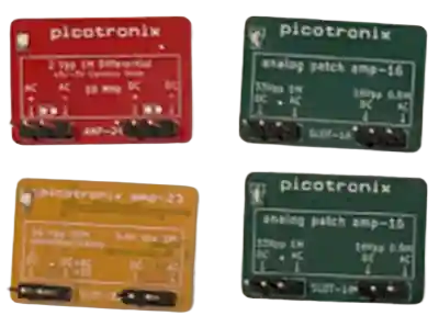
Each of the following functional categories of picoPods are available as Green or Yellow PCBs. Each colour is also available with a female header on the picoPod for direct coupling with the Picotronix Command Module or as a tentacle version that provides additional mobility by attaching it to the Command Module via a cable. Yellow typically connects to Port A, Green to Port B for visual clarity, but either colour works in either port.
• Primary Input: 1MΩ, ±5V range
• Measurement Window: 500mV span, adjustable anywhere within ±5V
• Alternate Input (BNC): 10MΩ, ±50V capability (AC x10, DC x10) – uncompensated
• Alternate Measurement Window: 5V span, adjustable under program control anywhere within +/- 50V
• Output: 0-3V to "The Platform" (representing selected 500mV or 5V span)
• Default Auto Config Setting: DC, Measurement Window 500mV Centred on Zero volts.
Available: Green/Yellow, Direct plug (B) or Tentacle (C) versions
• Primary Input: 1MΩ, ±5V range
• Measurement Window: 1V span, adjustable anywhere within ±5V
• Alternate Input (BNC): 10MΩ, ±50V capability (AC x10, DC x10) – uncompensated
• Alternate Measurement Window: 10V span, adjustable under program control anywhere within +/- 50V
• Output: 0-3V to "The Platform" (representing selected 1V or 10V span)
• Default Auto Config Setting: DC, Measurement Window 1V Centred on Zero volts.
Available: Green/Yellow, Direct plug (B) or Tentacle (C) versions
Each of the following functional categories of picoPods are available as Green (A) or Yellow (B) PCBs. Each colour is also available with a female header on the picoPod (B) for direct coupling with the "The Platform" or as a tentacle version (C) that provides additional mobility by attaching it to "The Platform" via a cable. Green typically connects to Port A, Yellow to Port B for visual clarity, but either colour works in either port.
• Primary Input: 1MΩ, ±5V range
• Measurement Window: 2V span, adjustable anywhere within ±5V
• Alternate Input (BNC): 10MΩ, ±50V capability (AC x10, DC x10) – uncompensated
• Alternate Measurement Window: 20V span, adjustable under program control anywhere within +/- 50V
• Output: 0-3V to "The Platform" (representing selected 2V or 20V span)
• Default Auto Config Setting: DC, Measurement Window 2V Centred on Zero volts.
Available: Green/Yellow, Direct plug (B) or Tentacle (C) versions
• Primary Input: 1MΩ, ±5V range
• Measurement Window: 5V span, adjustable anywhere within ±5V
• Alternate Input (BNC): 10MΩ, ±50V capability (AC x10, DC x10) – uncompensated
• Alternate Measurement Window: 50V span, adjustable under program control anywhere within +/- 50V
• Output: 0-3V to "The Platform" (representing selected 5V or 50V span)
• Default Auto Config Setting: DC, Measurement Window 5V Centred on Zero volts.
Available: Green/Yellow, Direct plug (B) or Tentacle (C) versions
The following functional picoPod is available as Green (A) or Yellow (B) PCBs. Each colour is also available with a female header on the picoPod (B) for direct coupling with 'The Platform" or as a tentacle version (C) that provides additional mobility by attaching it to "The Platform" via a cable. Green typically connects to Port A, Yellow to Port B for visual clarity, but either colour works in either port.
• Primary Input: 500K/10pf, -13.6V to +16.6V, DC and AC coupling options
• Measurement Window: 16.6 V adjustable under program control anywhere within Primary Input Range
• Alternate Input: 1M/10pF, -27.2V to +33.3V, DC and AC coupling options
• Alternate Measurement Window: 33.3V adjustable under program control anywhere within the Alternate Input Range.
• Zero Level is Stable: Negative bias circuitry ensures zero reading with no probe/open circuit
• Default Auto Config Setting: DC, Measurement Window 16V Centred on Zero volts.
Available: Green/Yellow, Direct plug (B) or Tentacle (C) versions
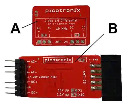
• AC and DC Differential inputs to 1MΩ at 10pf with a maximum difference of -1V to +1V between the two inputs
• Analog Range: 2Vpp
• Analog Common Mode: -5V to +5V
• Analog Gain : x1.5
• Analog Offset: +1.5V
• Default Auto Config Setting: DC, Measurement Window 2V Centred on Zero volts.
Available: AMP-24 Plugs directly into the Analog Port. AMT-24 Tentacle version attaches to the Analog Port via a cable.
• AC and DC Differential inputs to 1MΩ at 10pf with Two Analog Ranges:
11.1 Vpp X1
• Analog Gain X1.5
• Analog Offset +1.5V
1.11 Vpp X10
• Analog Gain X15
• Analog Offset +1.5V
• The range may be selected under software control.
Green LED Active for X1 Range Selected
Yellow LED Active for X10 range Selected
• Common Mode +/- 25V
Only available as a Tentacle Pod for coupling to "The Platform" by cable.
This picoPod provide 12 digital inputs to "The Platform" that are buffered and pulled to a known value if left floating.
It may be sampled at 150 MSPS – the maximum clock rate of the RP2350.
The inputs are divided into Three 4-bit Ports. Each Port may be connected to the same type of family as another Port or to a different type of family.
• For example, one Port may be for 3.3 volts and another for 2.5volts and a third for 5 volts, or two or more Ports may be the same (i.e., any combinations of 1.8V, 2.5V, 3.3V or 5V).
• The logic family for each Port is selected by a jumper across pins 9 and 10 of the Port or by supplying the family power supply onto pin 10.
The ADC-10 picoPod attaches to the Multifunction Port to provide Two 20 Mega Samples per second (MSPS) 8-bit Analog to Digital Converters.
The Pod may be configured to concurrently sample Analog Channels A and B at 20 MSPS each.
Alternatively a single channel selected from either of the Channels, may directed to both of the ADC's. By sampling the first ADCs during a first cycle of the clock and sampling the second ADC during the alternate clock cycle, an effective 40 Mega Samples /sec for the chosen channel is obtained.
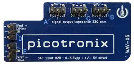
The Wave-05 12-bit DAC can generate an analog signal with a programmable Vpp that may be software controlled from 10mVpp up to 3.3Vpp.
Attaches to the Multifunction Port of "The Platform".
A software programmable offset may be applied to the generated analog signal to slide its Vpp window anywhere within a minus 5 volt to plus 5 volt range.
Three distinct 3-pin output ports for the generated signal are provided:
Positive Signal (A)
Negative reflection of the generated Signal (B)
Differential Signal (C)
The output ports (A, B, C) are compatible with our BNC Breakout Module (coming), enabling a BNC probe to be used to inject the generated signal into a circuit (handy!)
In addition to the 12-bit DAC, the Pod includes Two programable precision voltage reference generators:
Positive Vref: 250mA, 0 to Plus 5.12 volts (D)
Negative Vref: 20mA, 0 to Minus 5,12 volts (E)
The Wave-05 may be configured for flexible wave generation. For example, a State Machine using eight GPIOs of the RP2350 may drive the top 8-bits of the DAC to create a waveform of 8 bits resolution, a second State Machine using another 4 bits may be used to inject another signal (4 bits resolution) onto the main signal (e.g., to generate programmed noise).
A modular, low-cost test and measurement platform for makers, combining oscilloscope, logic analysis and extensible capabilities.
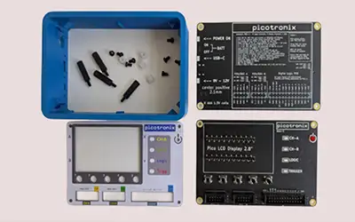
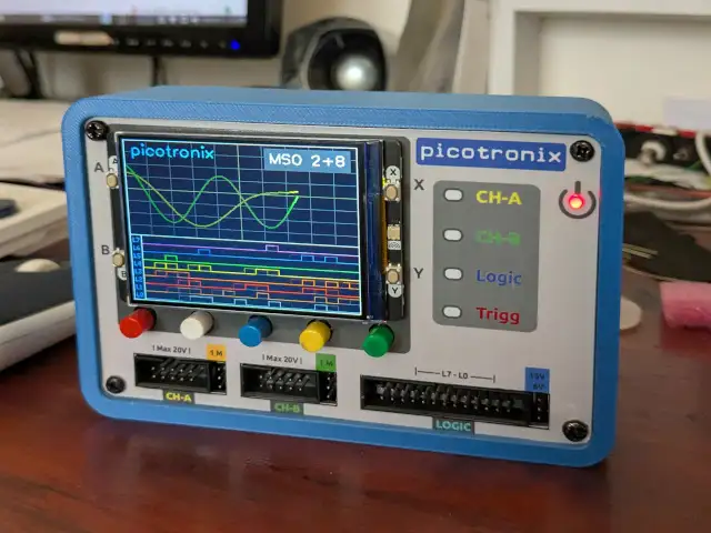
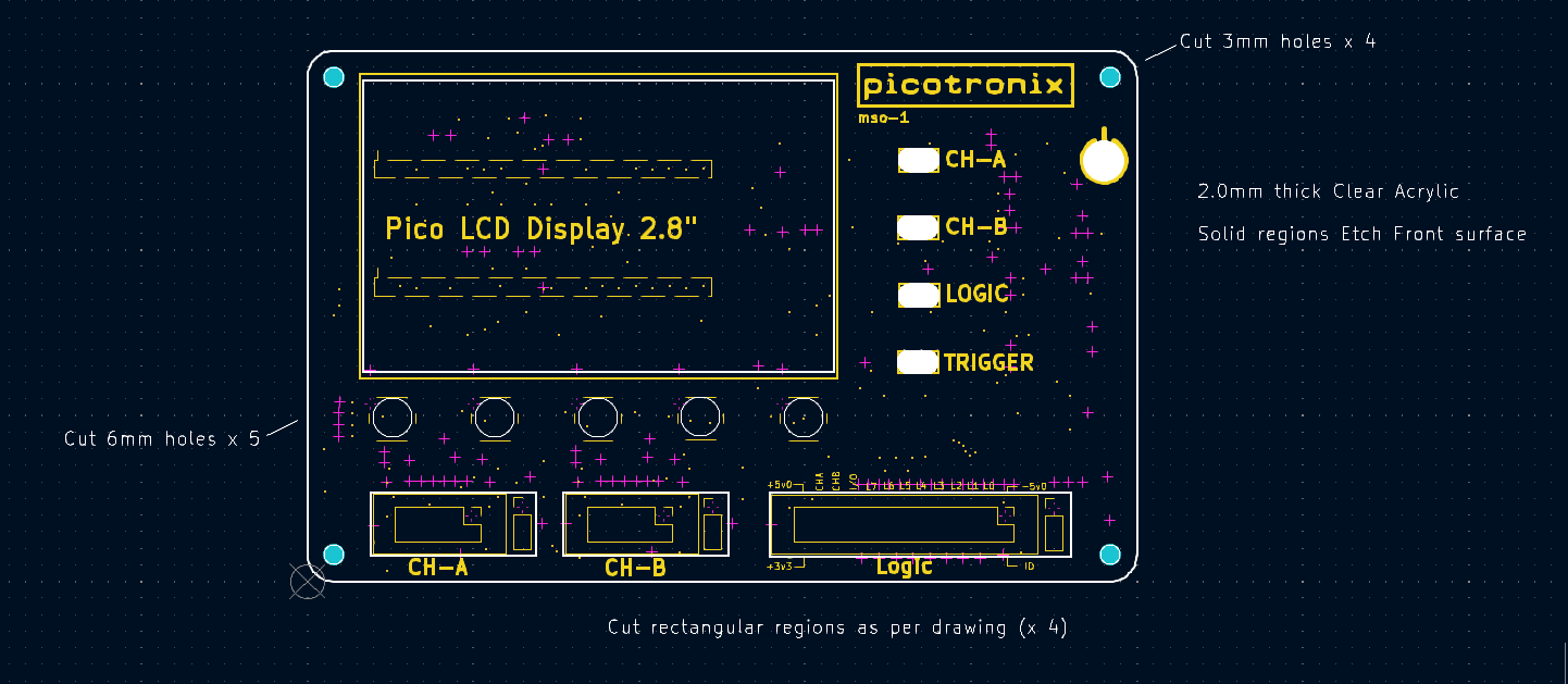
A Test Instrument that is part of an Electronics Workbench needs to have a case. This makes it portable, robust, and protects the internal circuits. The case design we came up with is a simple…
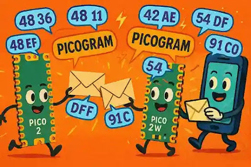
Distributed Pico system using msgpack "picograms" for modular, decoupled communication.
Get launch alerts, behind the scenes updates and get advance notice of early-bird specials